


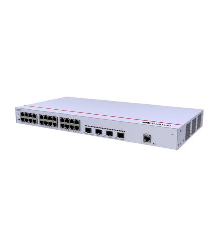

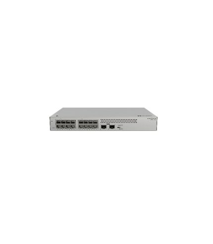
Huawei S310-24ST4X 24 SFP ports Switch
₦1,665,636.00
Components

| 1 | One MODE button | 2 | Sixteen 100/1000BASE-X ports |
| 3 | Eight Combo ports (100/1000BASE-X optical ports and 10/100/1000BASE-T electrical ports) NOTE: In the default working mode, the electrical ports in the combo ports are available. | 4 | Four 10GE SFP+ ports |
| 5 | One console port | 6 | One ETH management port |
| 7 | One RST button NOTICE: To restore the factory settings and reset the device, hold down the button for at least 6 seconds. To reset the device, press the button. Resetting the device will cause service interruption. Exercise caution when you press the button. | 8 | Ground screw NOTE: It is used with a ground cable. |
| 9 | Jack for AC power cable locking strap NOTE: The AC power cable locking strap is not delivered with the switch. | 10 | AC socket NOTE: It is used with an AC power cable. |
Ports
| Port | Connector Type | Description | Available Components |
|---|---|---|---|
| 100/1000BASE-X port | SFP | A 100/1000BASE-X port can send and receive data at 100/1000 Mbit/s. |
|
| Combo port (10/100/1000BASE-T + 100/1000BASE-X) | RJ45/SFP | A combo port refers to a pair of ports consisting of an optical Ethernet port and an electrical Ethernet port on the panel. Each combo port matches only one internal forwarding port. A combo port can be configured as an electrical port or an optical port, but only one port can be active at a time. When one port is active, the other port is shut down. |
|
| 10GE SFP+ optical port | SFP+ | A 10GE SFP+ Ethernet optical port supports auto-sensing to 1000 Mbit/s. It sends and receives service data at 1000 Mbit/s or 10 Gbit/s. |
|
| Console port | RJ45 | The console port is connected to a console for on-site configuration. | Console cable |
| ETH management port | RJ45 | You can connect a switch to a configuration terminal or network management workstation through the ETH management port to configure the switch locally or remotely. | Ethernet cable |
Indicators and Buttons

Description of indicators on the switch
| No. | Indicator | Name | Color | Status | Description |
|---|---|---|---|---|---|
| 1 | PWR | Power module indicator | – | Off | The switch is powered off. |
| Green | Steady on | The power supply is normal. | |||
| 2 | SYS | System status indicator | – | Off | The system is not running. |
| Green | Fast blinking | The system is starting. | |||
| Green | Steady on | During the system startup preparation phase, the SYS indicator is steady green, which lasts for a maximum of 30 seconds. | |||
| Green | Slow blinking | The system is running normally. | |||
| Red | Steady on | The system does not work normally after registration, or a fan alarm or a temperature alarm has been generated. | |||
| 3 | MST | Stack indicator | – | Off |
|
| Green | Steady on | The stack mode is selected. The switch is a standby or slave switch in a stack, and the service port indicators show the stack ID of the switch. | |||
| Green | Blinking |
| |||
| 4 | MODE | Mode switch button | – | – |
If you do not press the MODE button within 45 seconds, the service port indicators restore to the default mode. NOTE: Hold down the mode switch button for 6s and release it to start the web initial login mode. Either of the following situations will occur:
|
| 5 | CLOUD | Cloud indicator NOTE: In versions earlier than V600R024C00, this indicator is reserved. | – | Off | The management VLAN of the device does not obtain an IP address. |
| Blue | Steady on | The network is connected, and the management VLAN of the device obtains an IP address. | |||
| Blue | Fast blinking | The device is connecting to the cloud. | |||
| Blue | Slow blinking | The device is in the cloud management state. | |||
| 6 | – | Optical service port indicator (two indicators for each port) | Each optical port has two single-color indicators. The one on the left is the ACT indicator (yellow), and the one on the right is the LINK indicator (green). Arrowheads show the positions of ports. A down arrowhead indicates a port at the bottom, and an up arrowhead indicates a port at the top. | Meanings of service port indicators vary in different modes. NOTE: If a power failure occurs on a device’s PCB board, indicators of the last four GE or 10GE optical ports on the device’s front panel blink green cyclically at an interval of 1 second, with each indicator illuminating for 0.25 seconds.
| |
| 7 | – | Electrical or optical service port indicator (one indicator for each port) | Arrowheads show the positions of ports. A down arrowhead indicates a port at the bottom, and an up arrowhead indicates a port at the top. | ||
| 8 | ETH | ETH port indicator | – | Off | The ETH port is not connected. |
| Green | Steady on | The ETH port is connected. | |||
| Green | Blinking | The ETH port is sending or receiving data. | |||
Description of service port indicators in different modes (one indicator for each port)
| Display Mode | Color | Status | Description |
|---|---|---|---|
| Default mode | – | Off | The port is not connected or has been shut down. |
| Green | Steady on | A link has been established on the port. | |
| Green | Blinking | The port is sending or receiving data. |
| Brand |
Huawei |
|---|---|
| Solutions |
Datacom & Storage |
You must be logged in to post a review.


MAECENAS IACULIS
Vestibulum curae torquent diam diam commodo parturient penatibus nunc dui adipiscing convallis bulum parturient suspendisse parturient a.Parturient in parturient scelerisque nibh lectus quam a natoque adipiscing a vestibulum hendrerit et pharetra fames nunc natoque dui.
ADIPISCING CONVALLIS BULUM
- Vestibulum penatibus nunc dui adipiscing convallis bulum parturient suspendisse.
- Abitur parturient praesent lectus quam a natoque adipiscing a vestibulum hendre.
- Diam parturient dictumst parturient scelerisque nibh lectus.
Scelerisque adipiscing bibendum sem vestibulum et in a a a purus lectus faucibus lobortis tincidunt purus lectus nisl class eros.Condimentum a et ullamcorper dictumst mus et tristique elementum nam inceptos hac parturient scelerisque vestibulum amet elit ut volutpat.
Related products


Reviews
There are no reviews yet.